WinEEG and e-Prime connection
WinEEG and e-Prime should work on different computers. WinEEG works on WindowXP PC but ePrime works on Windows 98 PC!!! We will call WinEEG computer as recording computer and ePrime computer as presenting computer.
The main goal of connection is to synchronize the stimuli presentation process and EEG recording. e-Prime can send codes via COM port and WinEEG can catch this codes and recognize them as stimuli onsets.
That is why the next steps should be done to setup this connection.
1. Connect recording and presenting computers via COM ports using null-modem cable.
2. Modify e-Prime stimuli presentation script manually for e-Prime will send synchronization codes to COM port. The description of this procedure can be found in e-Prime manual. But shortly it is described below. e-Prime is able to send a characters (1 byte digits) to any IO port by special command of stimuli presentation script (see e-Prime manual). That is why e-Prime can directly program COM port. The programming of COM port can be found in any Programmer Manual for Serial IO port (COM port). Using this command e-Prime can configure COM port (set parameters of COM port) and send via COM port any information. To provide synchronization of EEG recording and stimuli presentation synchronization codes should be sent simultaneously with stimulus onsets. If single trial of task includes only one stimulus synchronization codes should be sent together with every stimulus onsets. If single trial includes several stimulus synchronization codes should be sent only together with first stimulus onset in trial. This means that only one synchronization code should be sent for each trial. Any synchronization codes (exclude “zero”) can be sent to WinEEG and WinEEG will use these codes as stimulus onsets and trial labels (stimulus types).
3. Define special synchronization mode in WinEEG. To do this run Setup->Equipment parameters command of main menu of WinEEG. The next dialog window will appear on the screen.
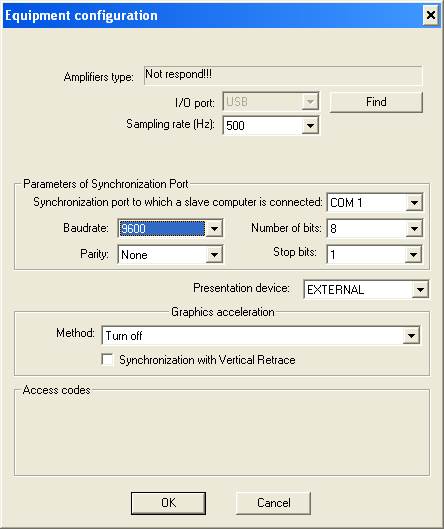
Following parameters of synchronization should be defined:
a. Synchronization port to which a slave computer is connected – in according to connection of presenting computer.
b. Baudrate, Number of bits, Parity and Stop bits – in according to settings of e-Prime. Usually it is not necessary to change these parameters on e-Prime computers. In this case Windows will use default settings. But these parameters should be defined in WinEEG, as displayed above. From the other hand it is strong recommended to check default settings of COM port parameters on ePrime computer.
c. Presentation device – select “EXTERNAL” option.
4. Run File->new command and open new EEG window.
5. Start EEG recording.
6. Run e-Prime stimuli presentation script
7. Look at bottom of the EEG window and check that stimuli marks (short vertical bars) are displayed synchronously with stimuli presentation.
WinEEG will automatically add trials for each synchronization code that WinEEG receive. The next parameters will be used by default: baseline time interval – 300 ms and duration of the trial 1000. These parameters can be changed using Edit->Trial labels command.
The next steps should be done to modify parameters of trials.
1. Open EEG file.
2. Run Edit->Trial labels command. Following dialog window will be displayed on the screen.
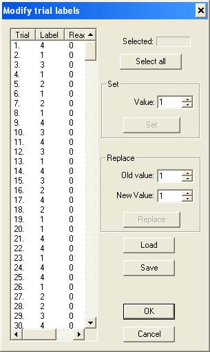
3. Press “Save” button to export parameters of trials to ASCII file.
4. Open generated ASCII file by Notepad. The possible content of this file is placed below.
StimuliList
  LeftLED S1 NoName
EndStimuli

Trial TR1 1000
  S1 300 100
EndTrial

Trial TR2 1000
  S1 300 100
EndTrial

PsyTest 640x480x256Colors LeftTop
  TR1 100 1
  TR1 100 1
  TR1 100 1
  TR1 100 1
  TR1 100 1
  TR1 100 1
  TR2 100 2
  TR1 100 1
  TR1 100 1
  TR1 100 1
EndTest

ResponseProcessing
EndProcessing
5. Modify description of trials for example as displayed below
Trial TR1 2000
  S1 300 100
  S1 1300 100
EndTrial

Trial TR2 1000
  S1 300 100
  S2 1300 100
EndTrial
In this case we define trial duration as 2000 ms. And trial includes two stimulus. First stimulus onset is equal 300 ms from beginning of trial and second stimulus onset – 1300 ms. The exposition of each stimulus is equal 100 ms.
6. Save these changes and close notepad.
7. Press “Load” button (see above) to import parameters of trials for opened EEG file.
8. Press “OK” button (see above).
9. Save EEG file using “File->Save” command.
Trial labels (coding stimuli types or conditions) can be change also. The example is placed below.
TR1 100 1 -> TR1 100 2
More detailed information can be found in PSYTASK user manual.
Warning!!! Never change other textual information of ASCII file. Incorrect ASCI file will be not loaded.
Warning!!! Never modify time onset of first stimulus. This will lead to mistake in ERP component latency measurement.
List of limitations of WinEEG – e-Prime system.
1. There is no way to change prestimulus time interval (baseline) in the trial. This time interval is fixed and equal 300 ms. It is not too strong limitation for many different task. 300 ms time interval is rather reasonable value for baseline correction.
2. Windows XP is not real time operation system. That is why some error in synchronization of EEG recording and stimuli presentation can be exists. To minimize this error use very power computers for EEG recording and close other application during EEG recording. More over it is strong recommended to turn off antivirus programs during EEG recording.
3. User should import new trials parameters for each new file. This is not a big deal but this is extra work.
There are not these limitations in WinEEG->PSYTASK system. We recommend you to learn PSYTASK features before you will begin the work with e-Prime.
Add serial port to e_prime
When StimTracker’s USB driver is installed, Windows will “see” a serial port device. This makes it possible to use StimTracker with any program capable of communicating with a serial port, including E-Prime.
This tech support note is in two parts: setting up E-Prime for communication with StimTracker, and how to send event markers via StimTracker. The screen snapshots were taken using E-Prime 2.0 and may look slightly different depending on the version you have.
Important: the instructions on this page assume that you have already installed the USB driver.
Setting Up E-Prime
In E-Studio:
• In the Structure window, double-click on Experiment Object; the Properties dialog (window) appears
• Click on the Devices tab
• Click on the Add… button; the Add Devices dialog appears:
• Double-click on Serial; this will add the Serial device and close the dialog
• Back in the Properties dialog, double-click on “Serial” to edit its properties:
• Change the “Bits per second” setting to 115200
• Set “COM Port” to match what the USB driver has set the COM port number to. E-Prime 1.x will let you use only port numbers between 1 and 4. To find out what is StimTracker’s COM port number or to change it so that it’s between 1 and 4, click here.
• [E-Prime 2.0 Only] It is tempting to rename the serial device from the default, generic “Serial” to something else, like “StimTracker”. If you do, then you must also change the function calls in E-Basic from Serial.WriteBytes and Serial.ReadBytes to StimTracker.WriteBytes and StimTracker.ReadBytes.
[E-Prime 2.0 Only] It is tempting to rename the serial device from the default, generic “Serial” to something else, like “StimTracker”. If you do, then you must also change the function calls in E-Basic from Serial.WriteBytes and Serial.ReadBytes to StimTracker.WriteBytes and StimTracker.ReadBytes.
• Click on OK when done to close the Serial Edit dialog
• Click on OK again to close the Properties dialog
This completes the basic setup. Serial port communication is now enabled within E-Prime.
Using StimTracker With E-Prime
Now it is just a matter of adding code to the task corresponding to the times that you would like E-Prime to have StimTracker put out an event marker. Before proceeding, please download the following file that contains a sample E-Prime experiment that was tested with E-Prime v2.0:
eprime_example [23KB]
In this example we will inform StimTracker of the onset of a stimulus display in each of the nine trials. Each event marker will communicate the value that is displayed on the monitor:
• Add an InLine object to the TrialProc immediately preceding the “StimDisp” Text Display object
• In this example, the InLine object that will send the serial communication is named “TrialInitInL”
Double-click on the “TrialInitInL” object and add the following code:
Dim integerVersionOfAttribute as Integer
Dim millisecondsDuration as Integer
Dim bytesThatMakePulseConfigCommand(5) as Integer
Dim bytesToRaiseStimTrackerLines(3) as Integer
Dim flagValueForDisablingPulse as Integer

millisecondsDuration = 30
‘ Just for fun, we will turn pulse OFF for the last few trials
flagValueForDisablingPulse = 16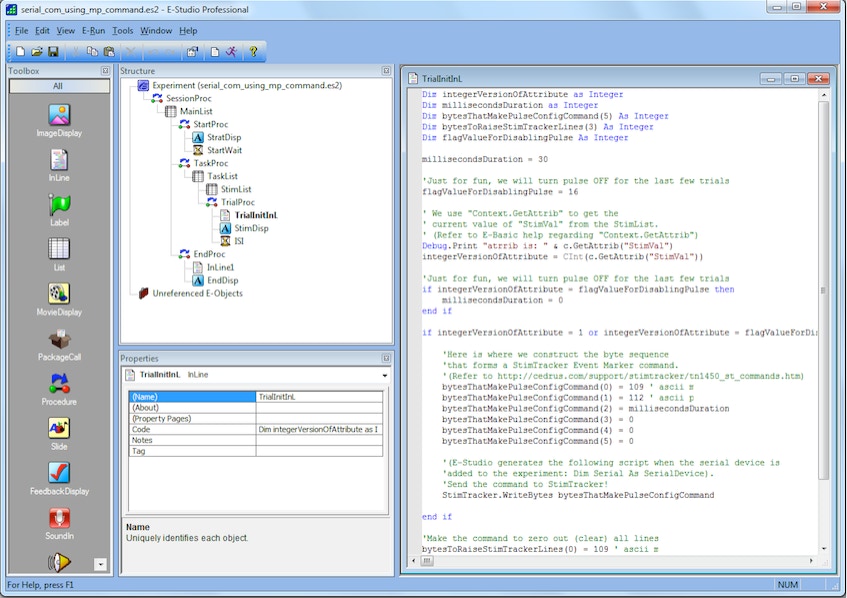
Move The Code to a Sub
Including the the code shown above every time you want to send a pulse can get tedious. You can move the code to an E-Basic sub and then just call the sub PulseStimTracker when you need to send a pulse:
‘ This function should be placed in the ‘User’ script area.
‘ View >> Script >> [choose ‘User’ tab]
Sub PulseStimTracker( lineSettings as Integer, millisecondsDuration as Integer )
Dim bytesThatMakePulseConfigCommand(5) as Integer
Dim bytesToRaiseStimTrackerLines(3) as Integer
‘ Here is where we construct the byte sequence
‘ that forms a StimTracker Event Marker command.
‘ (Refer to http://cedrus.com/pix/stimtracker/tn1450_st_commands.htm)
bytesThatMakePulseConfigCommand(0) = 109 ‘ ascii m
bytesThatMakePulseConfigCommand(1) = 112 ‘ ascii p
bytesThatMakePulseConfigCommand(2) = millisecondsDuration
bytesThatMakePulseConfigCommand(3) = 0
bytesThatMakePulseConfigCommand(4) = 0
bytesThatMakePulseConfigCommand(5) = 0
‘ (E-Studio generates the following script when the serial device is
‘ added to the experiment: Dim Serial As SerialDevice).
‘ Send the command to StimTracker!
Serial.WriteBytes bytesThatMakePulseConfigCommand
‘ Make the command to zero out (clear) all lines
bytesToRaiseStimTrackerLines(0) = 109 ‘ ascii m
bytesToRaiseStimTrackerLines(1) = 104 ‘ ascii h
bytesToRaiseStimTrackerLines(2) = lineSettings
bytesToRaiseStimTrackerLines(3) = 0 ‘ currently ignored by StimTracker
Serial.WriteBytes bytesToRaiseStimTrackerLines
End Sub
To copy code into the User Area of the script, select the User tab (located on the lower left corner of the Script editor window). Any code entered into this area is performed prior to the E-Studio compiled script at run time.
If the Script editing window is not visible in the E-Studio Workspace it can be accessed by checking View > Script from the E-Studio menu (or pressing Alt-5).
Verifying Firmware Version
Using the sample E-Basic code provided here requires that StimTracker be using firmware version SC05. All units shipped after December 1, 2010 have version SC05 (or later). Units shipped prior to this date will need to have the firmware updated. The following E-Basic code checks to see which firmware version your StimTracker unit has:
Dim incomingBytes(0) as Integer
Dim bytesRead as Long
Serial.WriteString “_d5″
Sleep 50 ‘ brief pause to make sure the command was received
bytesRead = Serial.ReadBytes(incomingBytes)
Debug.Print “Byte = “ & (incomingBytes(0) And 15) ‘ use 15 for a mask, binary 00001111
If the displayed version number is less than 5, then the firmware in the StimTracker unit needs to be updated.
Error Handling
You will notice that while using the configuration described above, the task will crash at run time if you do not have your StimTracker device connected and powered on. The “one2nine_disp_srlcom_ErrHdl.es” task (included in the compressed folder you downloaded earlier) adds a set up option to enable/disable serial communication as well as some more advanced operations that manage error handling and allow the user to make adjustments at run time.
Timing
Because this method of communication involves sending the serial event marker and then initiating the actual stimulus event in E-Prime separately, it is possible that delays can be introduced between the serial event marker and the actual stimulus event. For in depth information regarding critical timing within E-Prime consult your E-Prime user’s guide.
Credits
The work on providing E-Prime support to StimTracker and much of the write up for this tech note are courtesy of James Desjardins, Technician and MA student in the Brock University Cognitive and Affective Neuroscience Lab.