SmartBCI with SmartBOX setup for ERP recordings
SmartBCI with SmartBOX setup for ERP recordings
In Event Related Potentials (ERP) research with SmartBCI following accesosories may be used for proper data acquisition:
SmartBOX
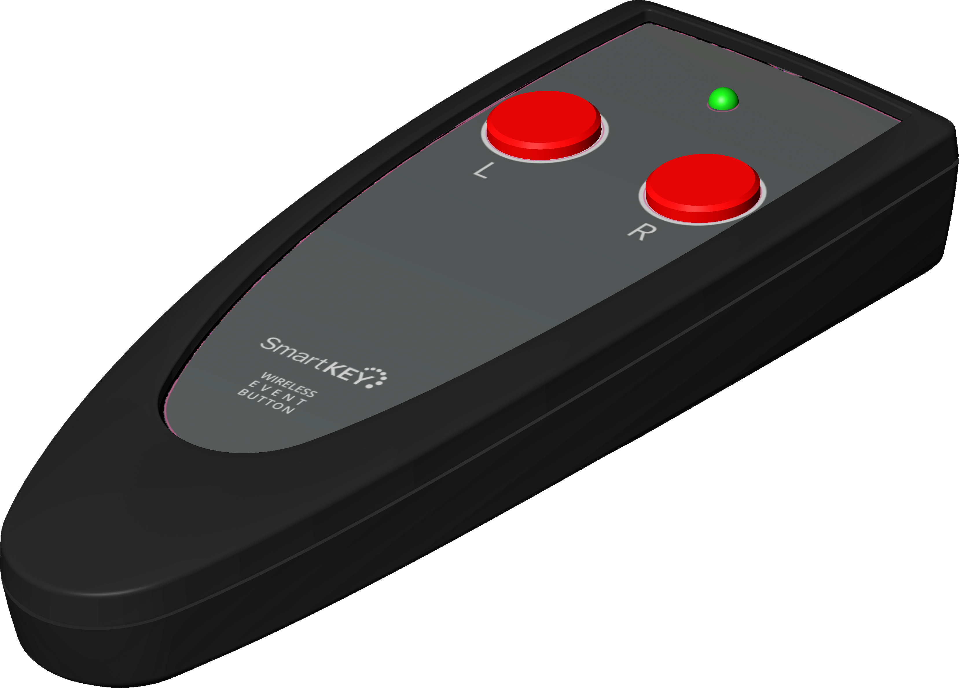
SmartKEY
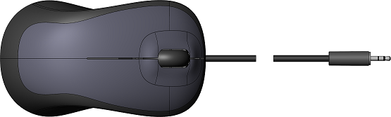
SmartPUSH
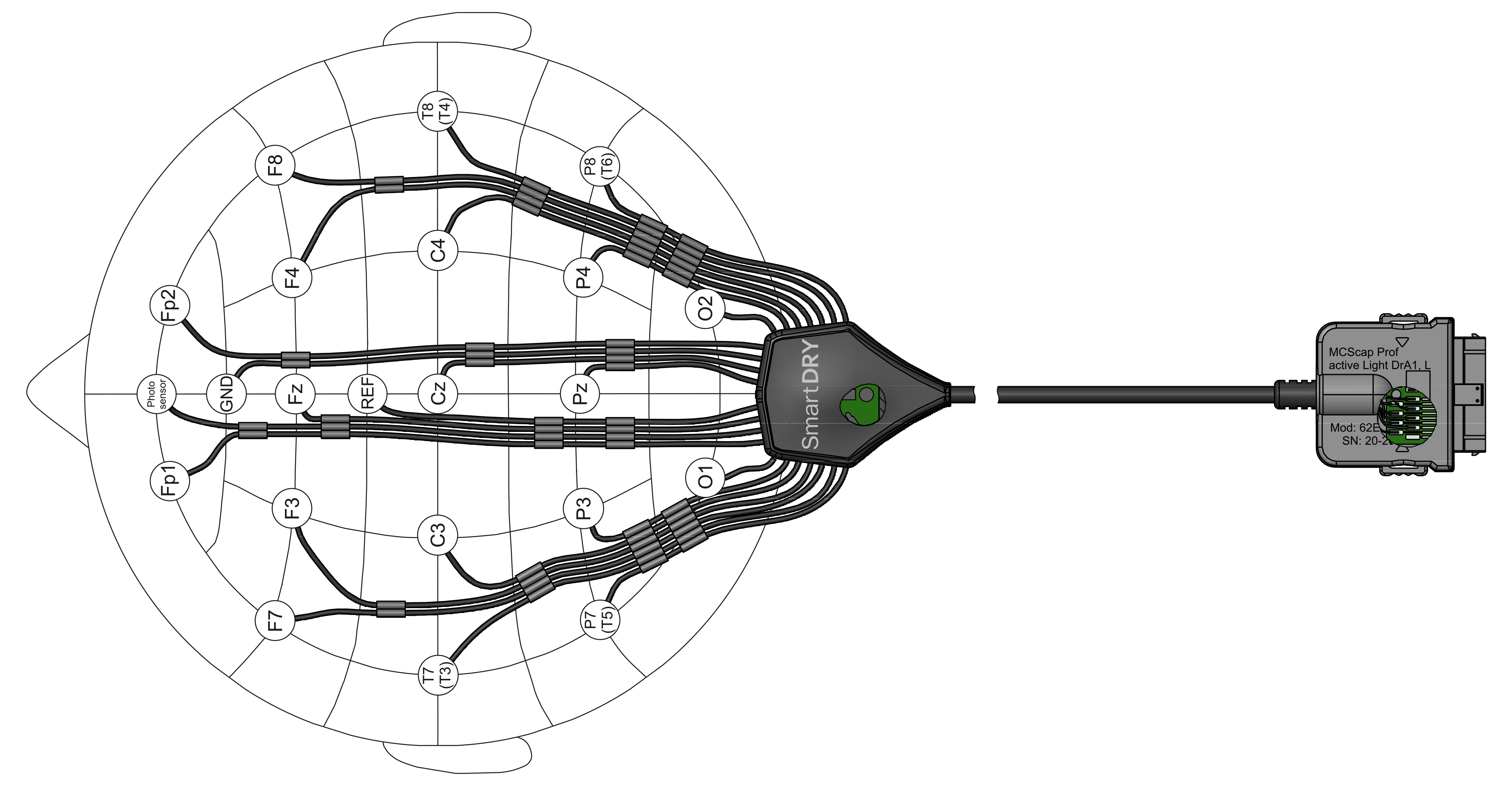
SmartCAP or SmartDRY caps
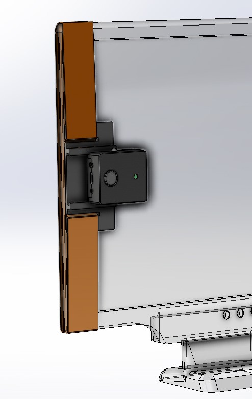
Below is a system setup for ERP recording. SmartBOX is attached to stimuli presentation monitor screen and detect actual visual stimuli presenation time using the special service field. SmartBOX is also connected to presentation computer audio output for audio stimuli detection. Event marks are wirelessly transmitted to SmartBCI unit via PSens located on the front lob of the EEG cap.
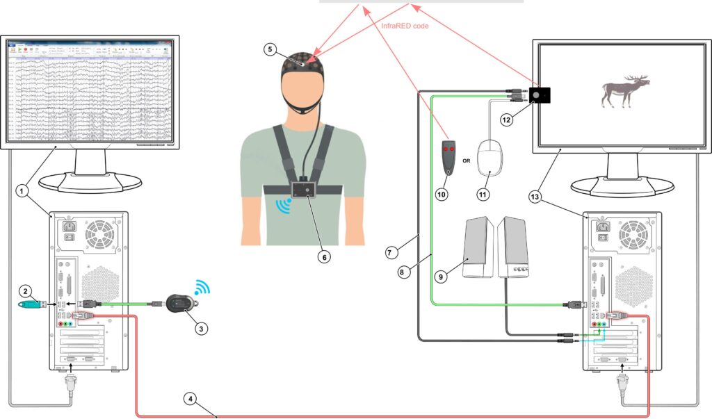
| 1. Master PC for EEG recording 2. Dongle with software license 3. SmartAIR wireless adapter (if required) 4. LAN cable to connect Master and Slave PC | 5. EEG cap with PSens 6. SmartBCI amplifier 7. Audio cable 8. USB cable 9. Speakers | 10. SmartKEY wireless button 11. SmartPUSH wired button 12. SmartBOX 13. Slave PC for stimuli presentation |
Patient respond can be detected using either wireless 2 channel SmartKEY or wired SmartPUSH buttons. SmartKEY button transmites patient respond marks directly to SmatBCI via PSens on the EEG cap. SmartPUSH button is connected to SmartBOX and patient respond data is transmitted via SmartBOX unit together with other event marks.
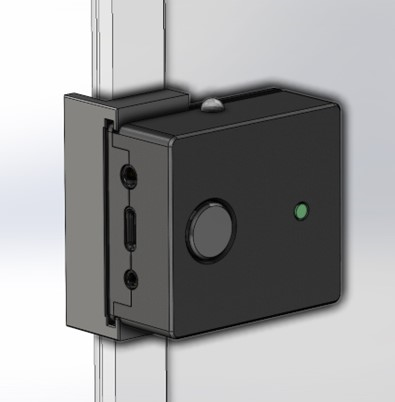
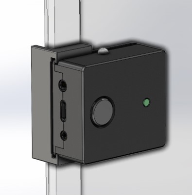
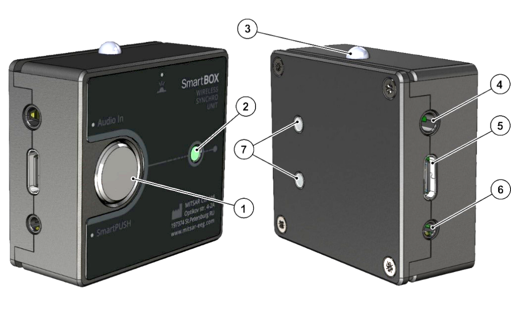
SmartBOX
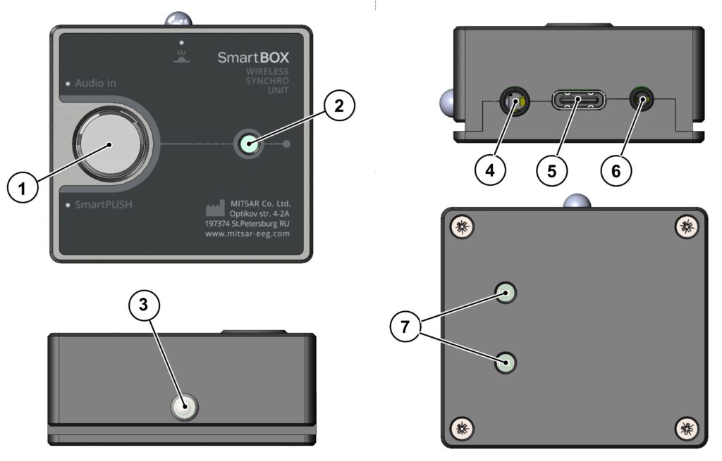
| 1. Turn ON button 2. Status LED indicator | 3. IR interface 4. Audio stimuli input | 5. USB Type-C interface 6. Connector for event button SmartPUSH 7. Visual stimuli detection sensor |
SmartBOX operation modes:
- A single short press of button [1] initiates the generation of a single synchronization trigger. The LED flash [2] indicates the moment of trigger transmission via IR interface [3].
- A double short press of button [1] activates the built-in periodic synchronization trigger generator with a 1-second period. The LED flash [2] indicates the moment of its transmission. Disable this mode by a short press of button [1].
- A long press of the button [1] (more than 1 second) switches the device to the mode of operation with video and audio stimuli for ERP recording. In this mode, the status indicator will permanently illuminate until the transmission of the first ERP stimulus, and thereafter, it will only flash at the moment of every single stimuli transmission. Disable the mode with a short press on the button [1].
SmartBOX operation procedure for ERP reseach:
- Connect provides the USB cable [8] to the SmartBOX connector [5] and to your computer’s USB port. When connected correctly, the SmartBOX status indicator [2] should flash briefly.
- Secure the SmartBOX to the monitor of the presenting computer using one of the methods (see mounting options for SmartBOX down below). The sennsor [7] of SmartBOX should be opposite the region where the stimuli presentation program (PSYTASK or analogue) presents the video pattern, ensuring that the alternating black and white fields are positioned opposite the two photoelements [7]. Adjust the size of the video pattern in the stimuli presenation program if necessary. The digital synchronization trigger is generated by switching the polarity of the patterns. Ensure that the IR interface LED [3] emits upward towards the ceiling or towards the PSens [5] of the EEG cap.
- If necessary, connect a wire from the SmartPUSH button to the connector [6] of SmartBOX, if the research algorithm also requires measuring the patient’s reaction time to the presented video and/or audio stimuli. Alternatively, you can use the wireless patient button, SmartKEY.
- Connect the PC audio output to the connector [4] of SmartBOX using an audio cable [7] through the audio splitter included in the package.
- Switch SmartBOX to the mode of operation with video and audio stimuli for ERP recording.
- Smart EEG recording and stimuli presenation required for ERP research. Be sure that stimuli and patient reaction marks are derected well and displayed in the EEG recording software as expected.
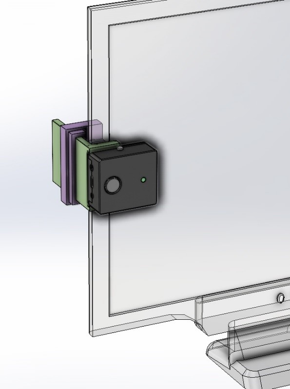
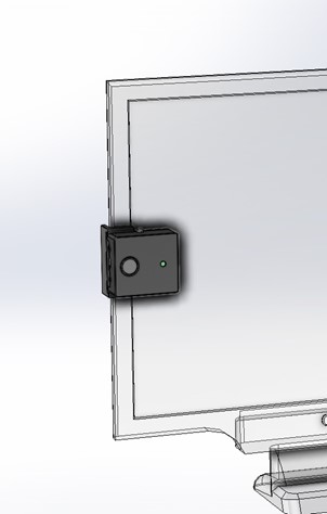
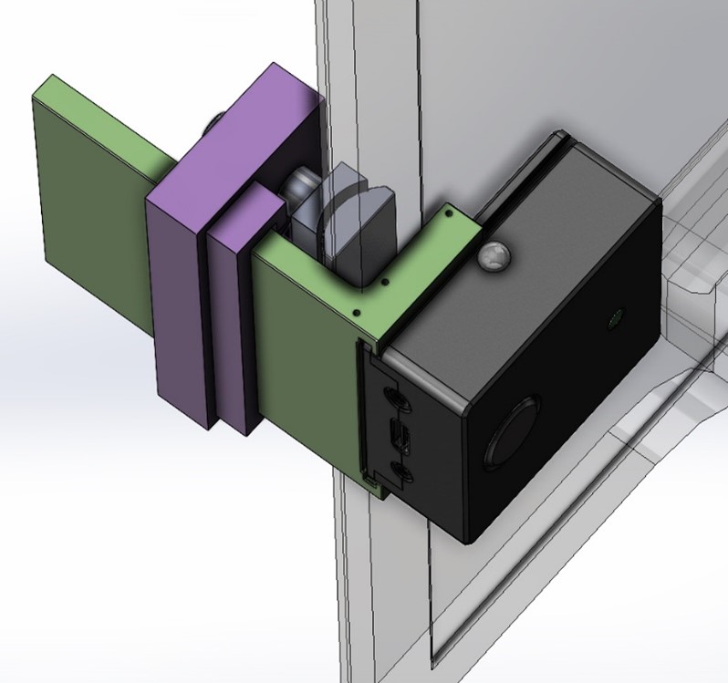
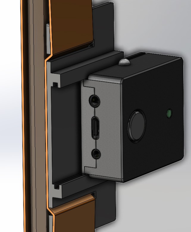
We offer a few options for SmartBOX mouting on the monitor screen. You can choose one that will fit you screen shapre better or get them all.
To perform calibration, follow these steps:
1, Connect the USB connector (Type C) [5] of the SmartBOX module and the USB socket (Type A) of the presenting computer with the appropriate cable provided. If the connection is correct, the status indicator [2] should blink.
2. Connect the presenting PC audio output with an audio cable to connector [4] of the SmartBOX module.
3. Mount the SmartBOX on the monitor of the presenting computer in one of the ways (see options for mounting the SmartBOX on the monitor) opposite the area where the PSYTASK program presents the video pattern (sync mark), so that the fields changing from black to white (and vice versa) are located opposite the two photo sensors [7].
If necessary, change the size and orientation of the video pattern in PSYTASK software. A digital code is generated by switching the polarity of the patterns. Make sure that the infrared LED [3] is emitting upward towards the ceiling or towards the photodetector (for example, the photodiode located on the MCS-Cap helmet). It is not recommended to use too bright lighting in the room where the SmartBOX module is used to avoid possible interference with the transmission of the infrared signal.
4. Press and hold the control button [1] for more than 1 second. The device will switch to the mode of working with patterns and sound stimuli. In this case, the status indicator will light up and remain lit until the first IR code is transmitted and then will flash only at the moment of IR code transmission when audio and/or video stimuli are presented. (Disable the mode by briefly pressing the button.)
5. On the presenting computer, run the Psytask program. In this case, a system of 2 computers must be configured: recording (WinEEG program) and presenting (Psytask program). See the info about ERP system configuration here https://mitsar-eeg.com/knowledge-base/wineeg-and-psytask-setup-for-erp/
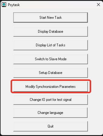
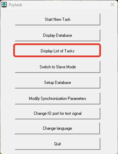
6. Select the menu item “Modify synchronization parameters”
7. Select the sync mark options as shown below:
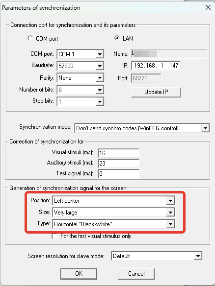
Press ОК.
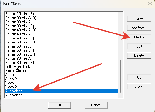
8. Set the required screen settings. To do this, select the “Display List of Tasks” menu item.
Then select the AudioVideo 1 test, click “Modify”.
In the “Image Processing” field, set the “Fit to Screen” option and click OK.
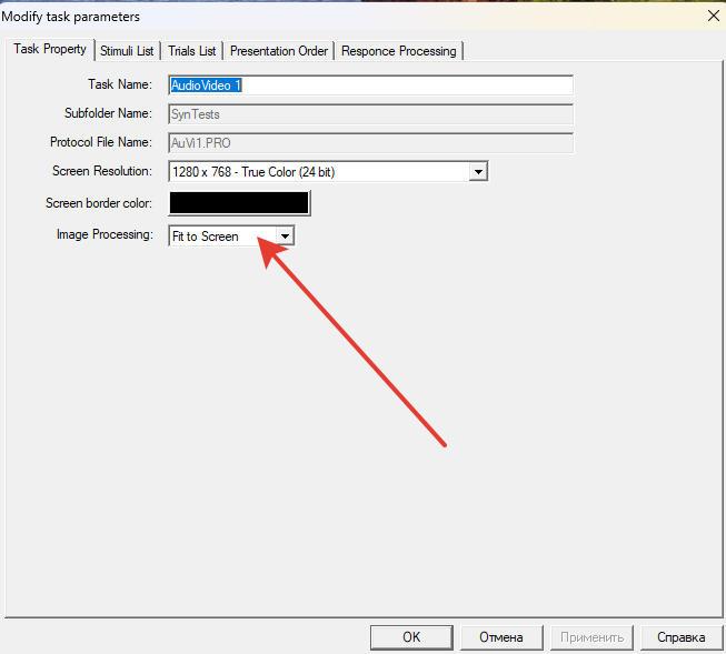
Close the “List of Tasks” window by clicking OK.
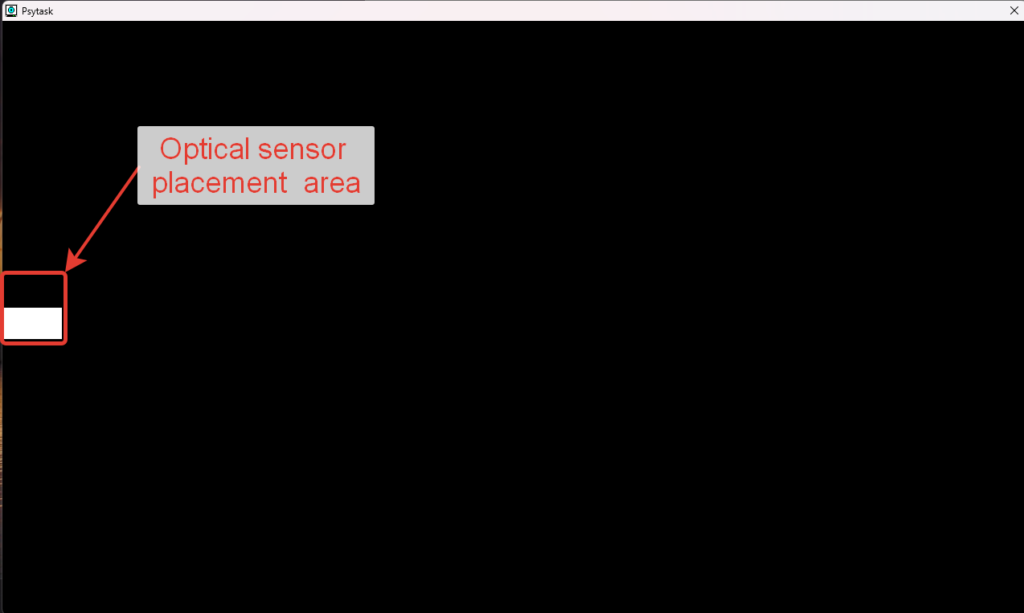
9. Check the correct location of the synchronization mark on the screen of the presenting computer. To do this, you need to run the AudioVideo 1 test. In Psytask, select the “Start New Task” Menu item. Next, in the list of tasks, select AudioVideo 1, click “OK”. The test will begin, and if the settings are made correctly, the program window will occupy the entire screen, and the synchronization mark will be in the middle of the left side of the screen.

10. Launch the Psytask program in slave mode (Menu item “Switch to Slave Mode”).
11. On the recording computer, launch the WinEEG program. Create a special montage for calibrating the ERP. To do this, open MENU – Setup – Montage List.
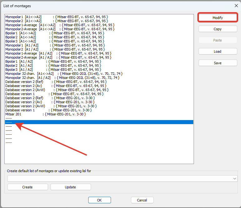
In the list of ready-made montages, select a free position (or any montage not used in your work)
and click the “Modify” button.
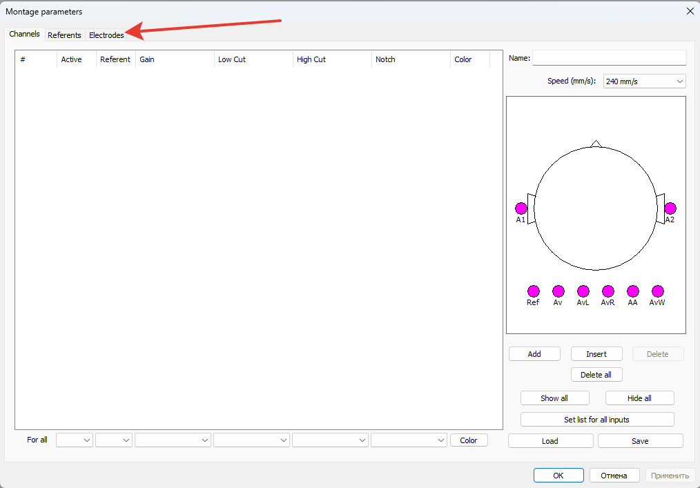
12. An empty montage window will appear. If an unused montage window opens, delete all montage lines using the “Delete All” button. Click on the “Electrodes” tab.
13. Select the necessary version of the device from the drop-down menu (it can be viewed in MENU – Setup – Equipment Parameters).
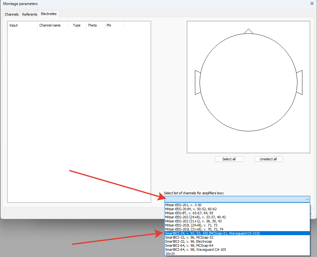
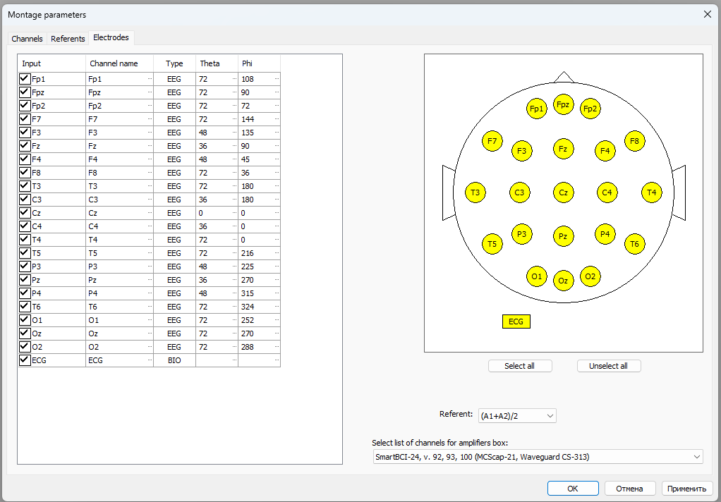
Press ОК.
A standard set of channels will appear.
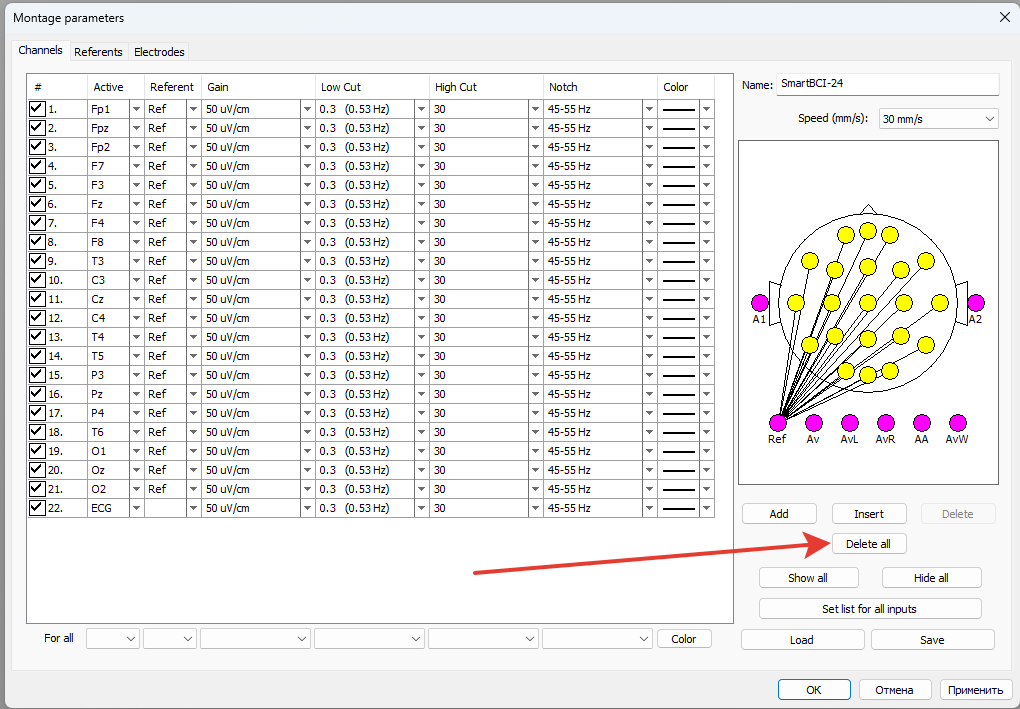
14. Go to the “Channels” tab
It will be necessary to delete all channels (the “Delete All” button), and then create two channels (audio and video) for the calibration signal.
After removing all channels, click the “Add” button twice. Two lines will appear to select channels. Click on the “Active” field in one of the lines. A list of possible channels will appear.
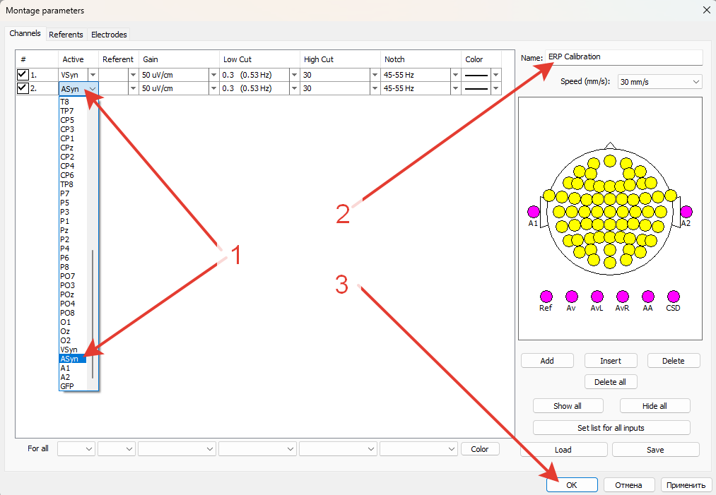
15. Select the channel named VSyn (arrow 1) in the channel list for the first line, and select the ASyn channel in the second line. Define the name of the montage, for example “ERP Calibration” (arrow2), click OK (arrow3).
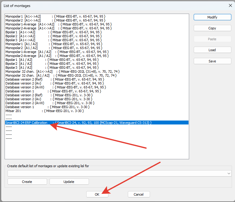
16. In the “List of montages” window, this montage will be highlighted in blue. Click OK.
This montage will now be loaded by default for a new patient.
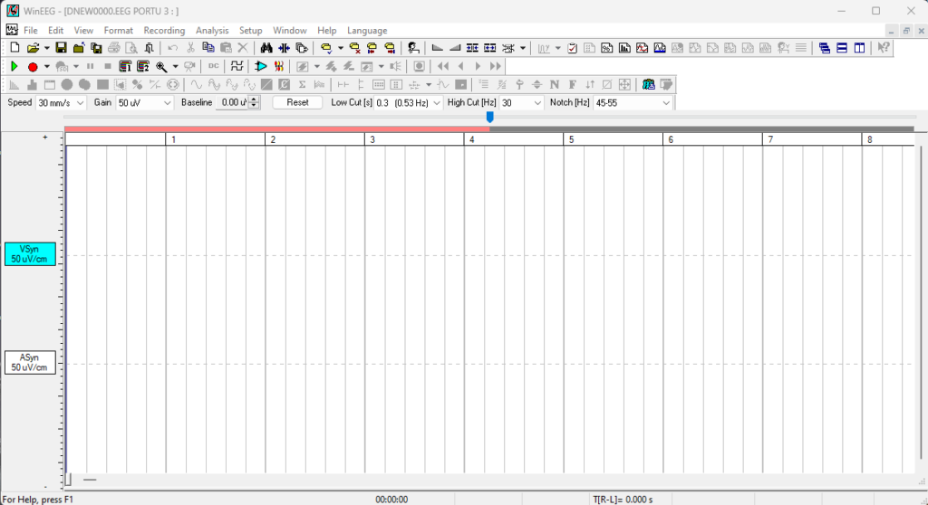
17. Create a new examination (MENU – File – New). A main program window will appear with a montage containing two channels – VSyn and ASyn.
18. Turn on the “Record” button (arrow 1), disable impedance measurement (arrow 2), then click the “Stimuli Presentation Program” button (arrow 3), select “AudioVideo 1” in the list of stimuli presentation protocols and click OK (arrow 4).
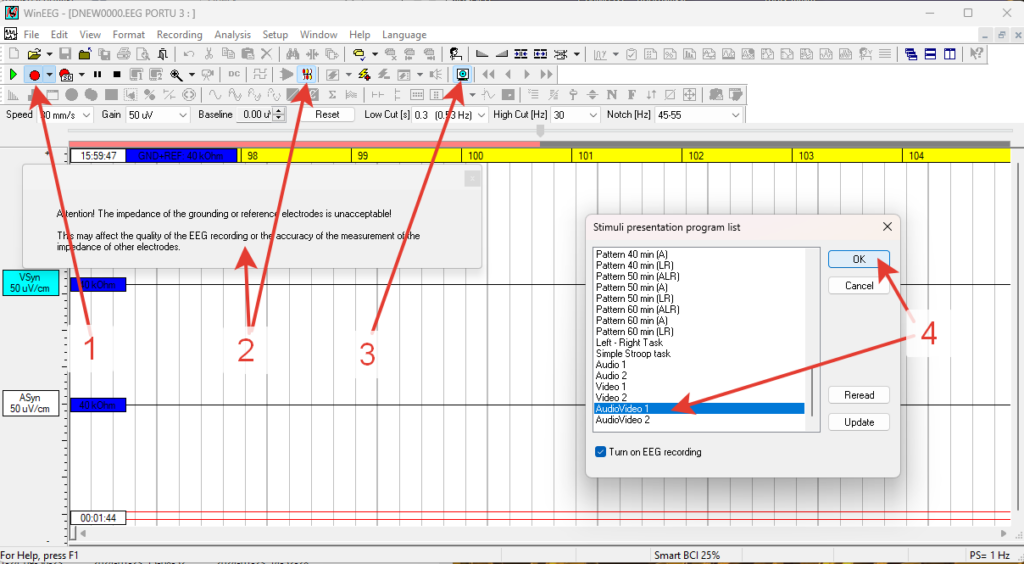
19. The corresponding test will start on the presenting computer. In this case, on the recording computer, the WinEEG program will record the signal from the synchronizing mark from the screen of the presenting computer via the VSyn channel, and pulses corresponding to sound stimuli via the ASyn channel. This should look like a series of 1000 pulses. Wait for the test to finish and stop recording with the button (Stop).
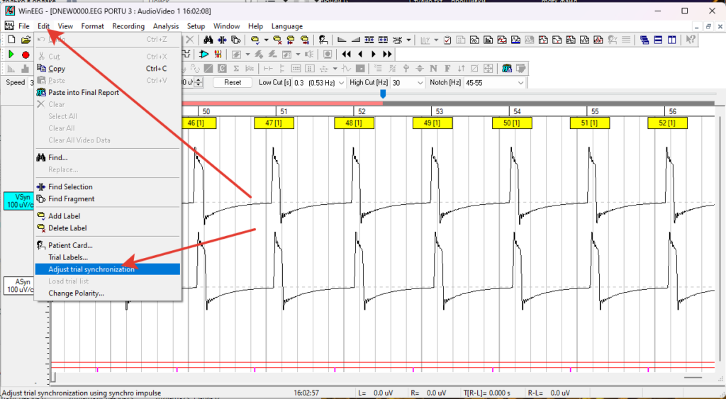
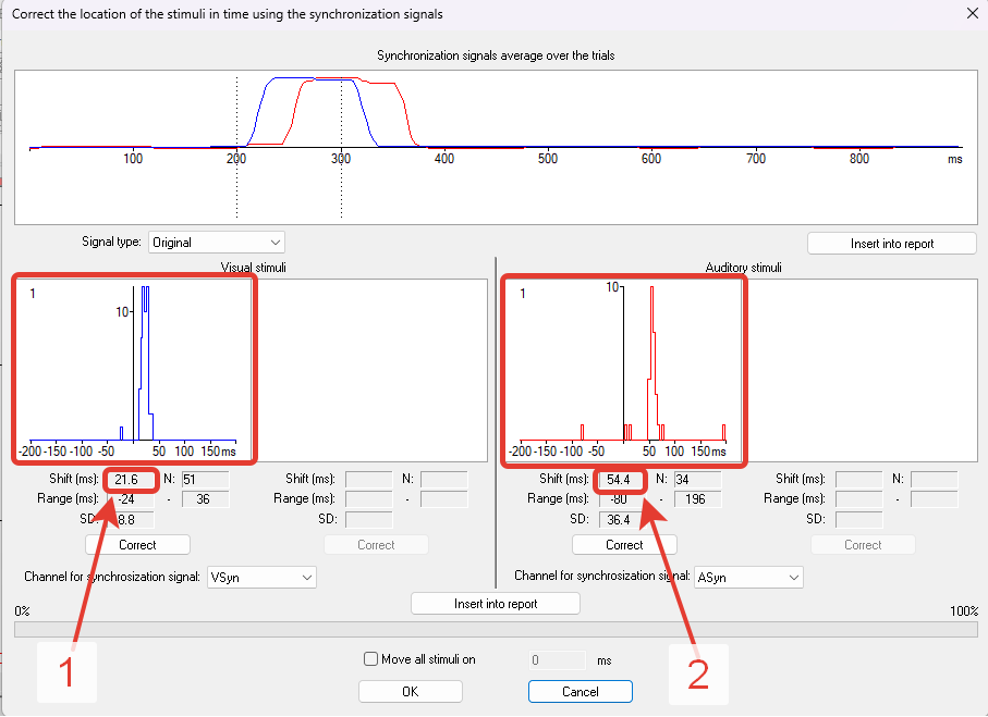
20. Open the “Edit” tab in the Menu and select “Adjust trial synchronization”. The window for measuring delay on video and audio channels will open. The left side of the screen displays a graph of delay distribution for the video channel, the right side is for the audio channel, and below, in the “Shift” field, the measured delay value for each channel is indicated (arrows 1 and 2, respectively).
21. These values, rounded to the nearest whole number, must be entered into the settings of the Psytask program on the presenting computer:
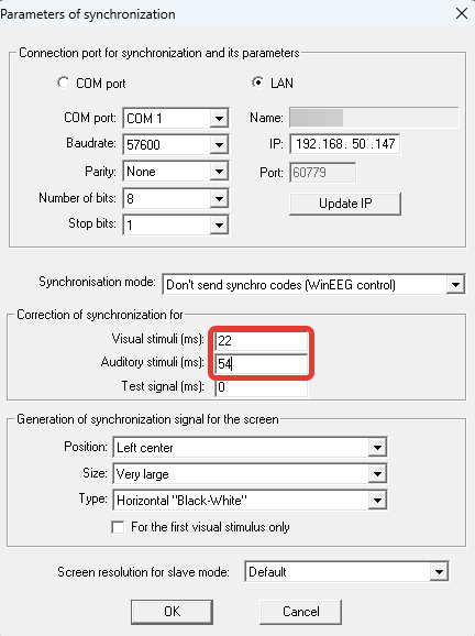
Press OK.
Thus, we compensate for the hardware delay and during subsequent recording of ERPs we measure only the latency of evoked potentials. Now you can turn off the flashing sync mark on the screen of the presenting computer. In the Psytask program, open the “Modify Synchronization Parameters” menu item and in the “Generation of Synchronization Signal for the Screen” section in the “Position” line, select the “Turn Off” option. Then click “OK”.
22. At this point, the calibration is completed, and you can begin to register the ERP using standard tests or tests developed independently.