Skip to main content
How Can We Help?
ERP calibration procedure w/ SmartBCI and SmartSYNC module
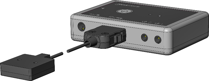
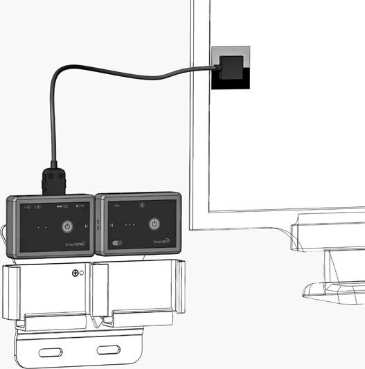
This combination of devices should be located near the presenting computer so that the SmartSENS optical sensor wire can reach the monitor freely. No EEG cap connection is required you can simple place them on the table.
3. Turn on the SmartBCI device by holding the "Power On/Off" button for a few seconds until all three LEDs light up.
4. Turn on the SmartSYNC device by holding the "Power On/Off" button for a few seconds until both LEDs (white and green) light up. If both devices interact correctly, the white LED on the SmartSYNC device will flash with double flashes.
5. Start the Psytask program on the presenting computer. The system should be set up with two computers: recording (WinEEG program) and presenting (Psytask program). Setup instructions can be found here: Link to Setup Instructions https://mitsar-eeg.com/knowledge-base/wineeg-and-psytask-setup-for-erp/
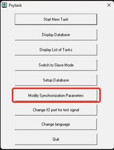
6. Select the Modify Synchronization parameters menu item
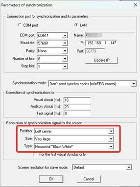
7. Select sync mark parameters as shown below:
Press ОК.
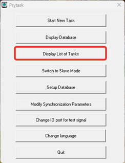
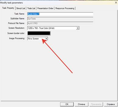
8. Set the necessary screen settings. To do this, select the Display List of Tasks menu item.
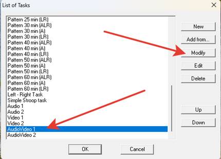
Then select the AudioVideo 1 test, click Modify.
In the Image processing field, set the Fit to Screen option and press OK.
Close the List of Tasks window by clicking OK.
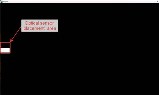
9. Verify the correct placement of the sync mark on the presenting computer screen. To do this, run the AudioVideo 1 test. In the Psytask program, select the Start New Task menu item. Then choose AudioVideo 1 from the tasks list and press OK. The test will start, and if the settings are correct, the program window will occupy the entire screen, and the sync mark will be in the middle of the left side of the screen.
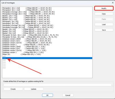
11. On the recording computer, launch the WinEEG program. Create a special montage for ERP calibration. Go to WinEEG - Setup - Montage List...
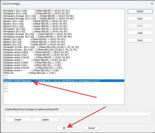
In the list of ready-made montages, choose a free position (or any montage not used in work) and click Modify.
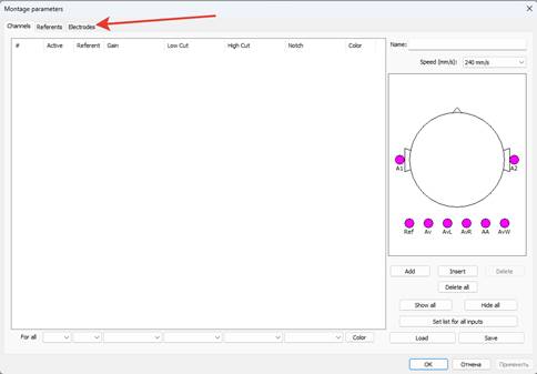
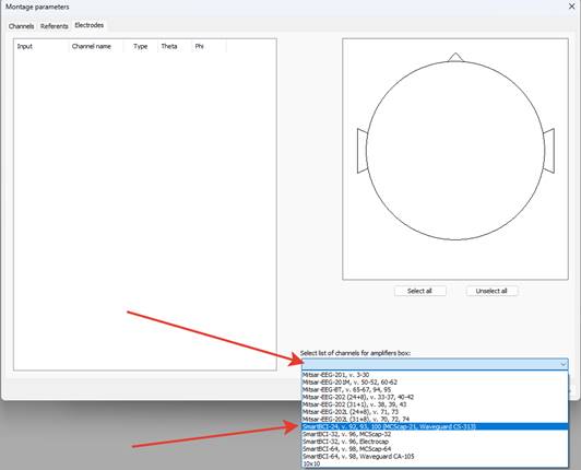
12. An empty montage window will appear. If the unused montage window opens, delete all montage lines using the Delete All button. Click on the Electrodes tab.
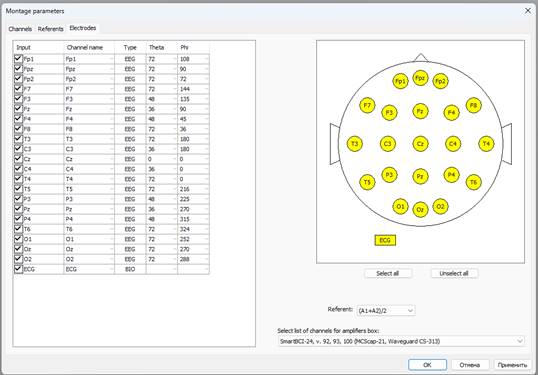
13. Choose the appropriate device version from the drop-down menu (you can find this version number in WinEEG - Setup – Equipment Parameters).
Press OK. A standard set of channels will appear.
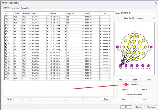
14. Switch to the Channels tab. You will need to delete all channels, then create one channel for video signal calibration.
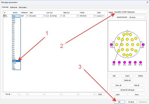
15. In the list of channels, select the channel with the name VSyn (arrow 1), specify the montage name, for example, ERP Calibration (arrow 2), and press OK (arrow 3).
16. In the List of montages window, this montage will be highlighted in blue. Press OK. Now, this montage will be loaded by default for a new patient.
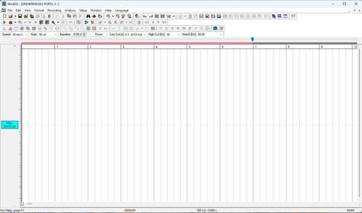
17. Create a new examination WinEEG - File - New. The program window will appear with a montage containing only one VSyn channel.
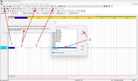
18. Turn on the Record button (arrow 1), disable impedance control (arrow 2), then click the Stimuli Presentation Program button (arrow 3). In the list of stimulus presentation protocols, choose AudioVideo 1 and press OK (arrow 4).
19. The corresponding test will start on the presenting computer. Meanwhile, on the recording computer, the WinEEG program, through the VSyn channel, will record the sync mark signal from the presenting computer screen. This should look like a series of pulses, around 1000 in total. Wait for the test to finish and stop recording with the Stop button 
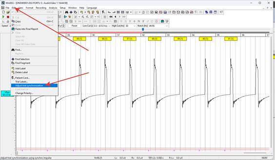
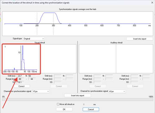
20. WinEEG drop down menu open the Edit section and select Adjust Trial Synchronization. The delay measurement window for the video channel will open. The left side of the screen displays the delay distribution graph, and below, in the Shift field, the measured delay value is indicated.
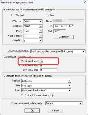
21. Round this value to the nearest whole number and enter it in the settings of the Psytask program on the presenting computer.
This is how we compensate delay of visual stimuli presentation in order to measure correct latencies of ERP.
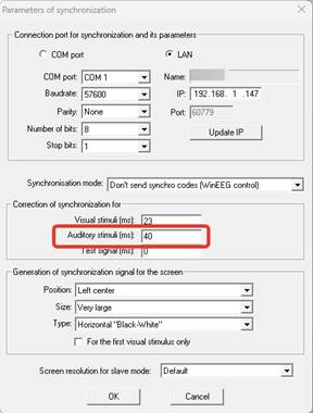
22. Since the SmartSync module does not have the technical ability to measure the delay over the audio channel, but there is, nevertheless, a delay, you need to enter a certain average value measured empirically in the corresponding field of the Psytask program. It is approximately 40 ms for most computers.